AutoChess: Self-Playing Chess Board
Orko Sinha and Alexander Drazic ECE 5725 - Embedded Operating System
Demonstration Video
Introduction
Almost everyone has heard of or played the game of chess. Chess is a classic game where two opposing players face each other with equal pieces and aim to capture the opponent's king piece. The issue with chess is that there needs to be two players. Online simulators of chess choose to remedy this problem by either matching other players through the Internet or placing the player against a bot. This solution, unfortunately, doesn’t allow the solo user to play with a physical chess board. To fix this problem, we created a chess board that you can play against. The chess board uses a Raspberry Pi and an array of sensors to determine the current state of the game and uses the award winning Stockfish chess engine as the user’s opponent.
Physical Design
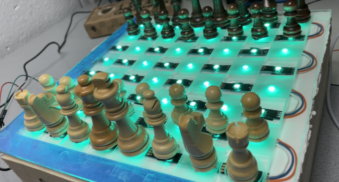
The physical design of the system was a process that required a lot of thought. We wanted to use LEDs to light up the opponents move and tell the user where they could move a piece. Therefore, a chess board that was semi-transparent and let light through was required. We used an acrylic board that was laser cut to engrave the board. This gave us the transparency we needed. We also needed a way for the Raspberry Pi to know where every piece was on the board. To solve this problem we used hall effect sensors and attached a neodymium magnet to the bottom of each chess piece. Additionally, we made a wooden structure for the board to sit on so that it was rigid. Rigidness was required due to how sensitive the hall effect sensors were. Thus, we needed a frame for the chess board that wouldn’t move around and provide stability.
Electrical Hardware Design
To tackle the challenges that this project posed, electrical design was critically important. Each square of the board needed to be able to read the pieces on the board, the user interface needed to be intuitive, and we were limited by the number of GPIO pins available. Hall effect sensors were used to read the board state, LED lights and a TFT screen enabled the UI to be intuitive, and a decoder was used to lessen the number of GPIO pins that were used.
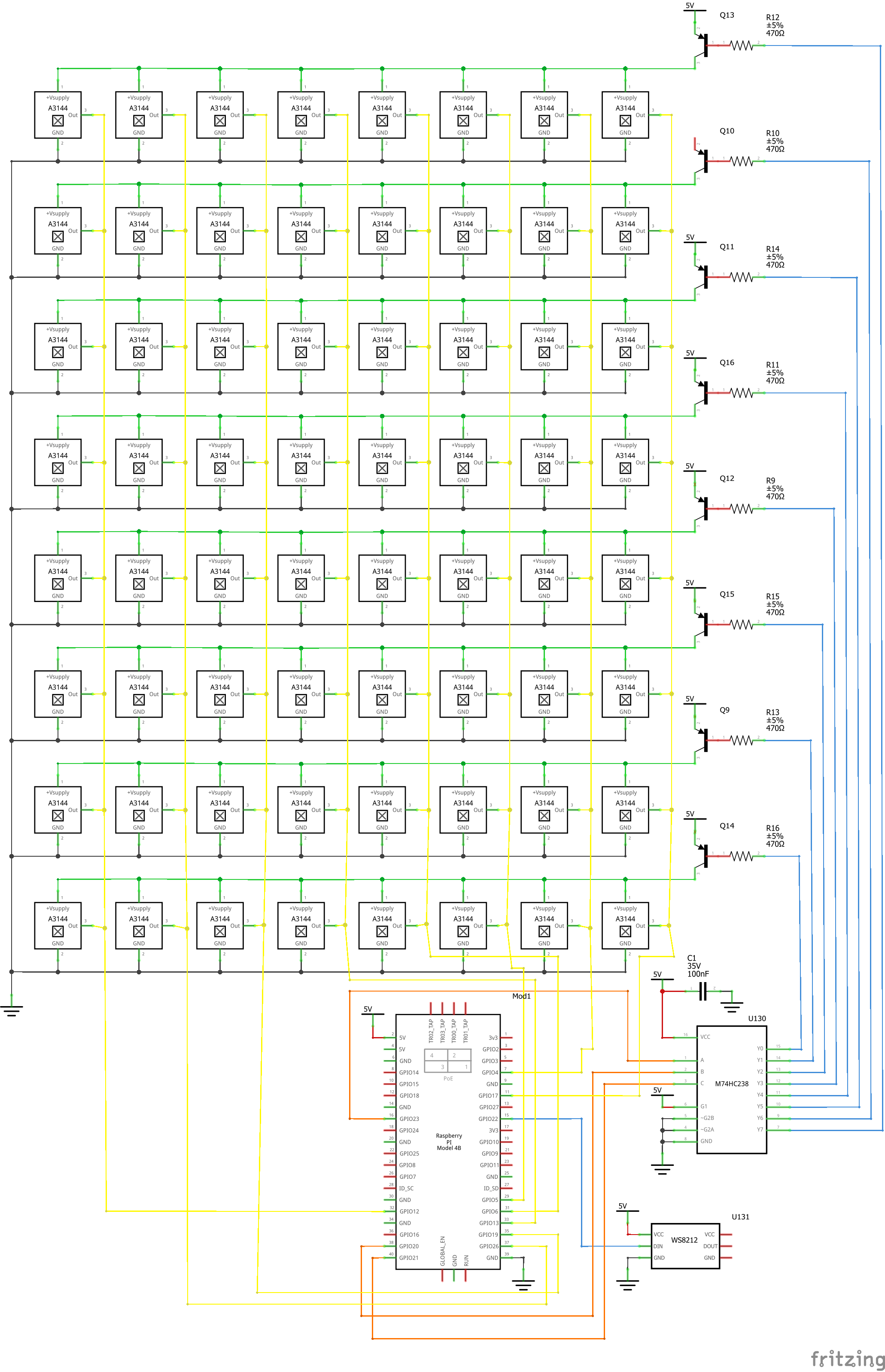
The circuit used was a grid of hall effect sensors that was activated with a decoder and PNP BTJs. Each column of the hall effect sensor grid was connected as an input to a Raspberry Pi GPIO pin. Each row of the hall effect sensor grid was connected to a 3:8 decoder output and PNP BJT. This system activates only one row of the hall effect sensor grid at a time. Thus, the entire board state can be read by activating one row at a time and then iterating through the columns. The following electrical schematic shows how the hardware was hooked up together.
LED Light Strips
Neopixel LED light strips were used to illuminate each square of the chess board. Neopixels are individually addressable and this functionality was used significantly. At the start of the game, the board illuminates either green or red to tell the user if the pieces are properly set or not, respectively. These lights were used to tell a user where a piece could move when it was picked up by lighting valid squares up in red. And finally, when the computer made its move, the piece and its destination square was lit up in blue for the user to move it themselves.
The LED strips are operated by using one GPIO pin and the Neopixel python library. Additionally, the lights needed to be stepped up to 5V with a level converter as the Raspberry Pi sends out 3V3 signals.
Decoder
The 3:8 decoder was one of the most critical pieces to this project. It reduced the number of necessary GPIO pins by a large amount. The three input pins were connected to the RPi through a level converter to scale up to 5V. The decoder outputs were then connected to a PNP BJT and 470 ohm resistor to allow for the activation of each row. The PNP BJTs act as switches and the resistors reduce current draw. Using this scheme, each output of the 3:8 decoder corresponds to a row of the chess board and only one row can be active at a time.
Hall Effect Sensors
The hall effect sensor grid was used to determine whether or not a piece was on a square. If a piece activated the hall sensor, a digital 0 was sent to the RPi. Every square had a hall sensor underneath it and these were connected through wire wrapping. As was mentioned before, one row was active at a time and then each column read the state of that sensor. The hall effect sensors, however, posed the biggest challenge to this project. These sensors have a short range and are very sensitive. Each piece needs to be placed directly on top of the sensor for it to be read properly. This challenge became a large issue because the magnets on the underside of the pieces naturally repel each other. A temporary solution of adding duct tape to the bottom of each piece was used because it increased the friction with the board.
Due to using hall effect sensors, the RPi has no knowledge of which pieces are where on the board. This limitation leads to the location of pieces being tracked internally through software and also requires that the initial location of pieces is correct.
Software
For the chess playing and chess state management, we relied on the Python library python-chess. This library simplified the state management associated with the game of chess, so the main task of our software was to manage the state of the board. The main software components of our board included managing the LED strip, the hall effect sensor grid, and the chess engine.
All of these different components communicate with each other by considering the chess board as a range of numbers 0 to 63. The number 0 corresponds to square A1, 1 corresponds square B1, and so on where 63 corresponds to H8.
LED Light Strips
We constructed a LEDMatrix class to simplify handling our LED strips. This class is mainly used to assign an individual square on the chess board a certain color.
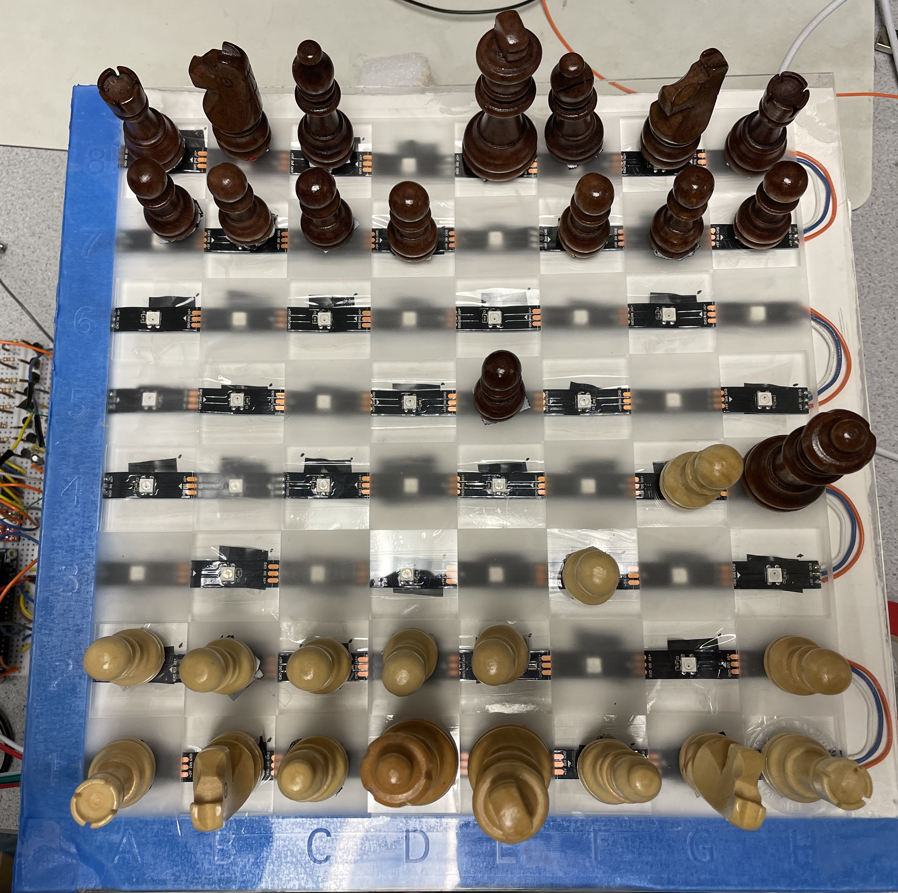
The LED strip is arranged in a "snake" pattern as pictured below, and the Neopixel library we used to interact with the LEDs uses a one dimensional array to assign individual LEDs to colors. This results in every other row having reversed indicies, which required some manipulation to correspond to the correct square when communicating with the other components of our project. We solved this issue by constructing a map of reversed indicies and queried it when encountering these problem rows.
Decoder and Hall Effect Sensors
We constructed a Decoder class to handle both getting information from the hall effect sensors and the decoder.
The first thing the Decoder class does on initialization is construct the start state which is hard set to knowing the first two and the last two rows are occupied by pieces. Since the hall effect sensors only can tell us whether a magnetic field is present, the only information we can gather from the hall effect sensors is that a piece is placed on a particular square.
The decoder is set to each row in a loop and then each column is checked individually which results in us being able to individually check whether each square is occupied or not. If the square's state is changed (as in it was occupied and is currently not occupied) we call a callback function which is passed to the Decoder class. This polling also occurs on a separate thread to not interfere with other logic.
Chess Engine and PyGame
Since our chess state is managed by the python-chess library, a good amount of overhead for checking legal moves, checking for win conditions, and managing the state of the pieces in-play is handled for us. The engine itself also queries Stockfish which is installed on the Raspberry Pi for CPU moves. However, we need to also maintain a sense of real world state with the board, and this is what mostly occurs in the main thread. Everytime the Decoder class sees a new event, a callback is called which increments the state (for example, if it is the white player's turn then the next square state change should be the white player making their move) and makes the main thread do different things with PyGame, so the user can see who's turn it is or whether they have lost etc, and with the chess engine.
Conclusion
Overall, this project was very fun and taught us a lot about circuit design and project planning. The circuit design was fun because we put a lot of components together and operated them in tandem. Though we’ve learned about each of these components individually, this project made us use them together and operate them as a system. Additionally, the GPIO constraints made us come up with a nice solution. This project taught us how important planning is to a successful project. Even though we began building and integration very late into the timeline, we knew exactly what needed to be done and we only had to test that everything worked as expected. This also led to few decisions being made at the moment. Finally, afte four hundred and eight connections, I have learned to never wire wrap something again. It was too much.